Database design
Objectives
- Use Entity Relationship Diagrams to visualise and structure your data.
Questions
- What is database design?
Spreadsheets
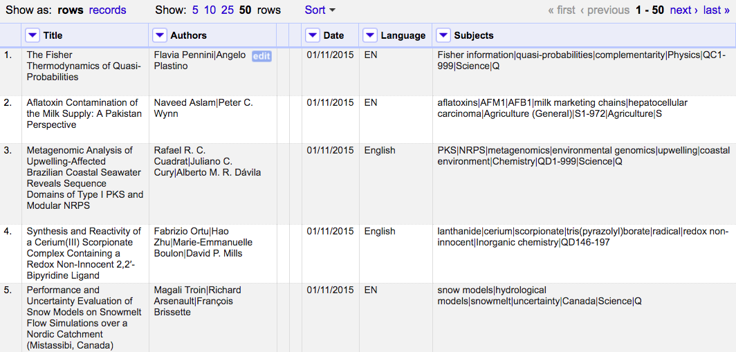
In libraries, spreadsheets are often created to keep lists of a variety of things like an inventory of equipment, reference statistics, or items to review for purchase (See What are some of the uses for SQL in libraries?). Spreadsheets, sometimes referred to as tabular data or flat files, are an easy way to display data organized in columns and rows. Column headers describe the data contained in corresponding columns. Each row is a record (sometimes called an observation) with data about it contained in separate column cells.
Spreadsheets can make data gathering easier but they can also lead to messy data. Over time, if you gather enough data in spreadsheets, you will likely end up with inconsistent data (i.e. misformatted, misspelled data).
Challenge
Identifying inconsistencies in spreadsheet data
In the figure below, can you identify where inconsistencies in the data have been introduced?
Designing a relational database for your data can help reduce the places where these errors can be introduced. You can also use SQL queries to find these issues and address them across your entire dataset. Before you can take advantage of all of these tools, you need to design your database.
Database Design
Database design involves a model or plan developed to determine how the data is stored, organized and manipulated. The design addresses what data will be stored, how they will be classified, and the interrelationships between the data across different tables in the database.
Terminology
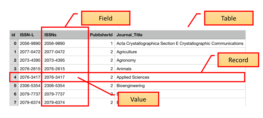
In the Introduction to SQL lesson, we introduced the terms “fields”, “records”, and “values”. These terms are commonly used in databases while the “columns”, “rows”, and “cells” terms are more common in spreadsheets. Fields store a single kind of information (text, integers, etc.) related to one topic (title, author, year), while records are a set of fields containing specific values related to one item in your database (a book, a person, a library).
To design a database, we must first decide what kinds of things we want to represent as tables. A table is the physical manifestation of a kind of entity. An entity is the conceptual representation of the thing we want to store information about in the database, with each row containing information about one entity. An entity has attributes that describe it, represented as fields. For example, an article or a journal is an entity. Attributes would be things like the article title, or journal ISSN which would appear as fields.
To create relationships between tables later on, it is important to designate one column as a primary key. A primary key, often designated as PK, is one attribute of an entity that distinguishes it from the other entities (or records) in your table. The primary key must be unique for each row for this to work. A common way to create a primary key in a table is to make an id field that contains an auto-generated integer that increases by 1 for each new record. This will ensure that your primary key is unique.
Tip
It is not always recommended to use auto-incremented integers as primary keys:
- Internaly, the incrementing must be done atomically to ensure uniqueness, which may slow done concurrent insertions to the database.
- The generated PK is not known before insertion, meaning the client has to query what was just inserted in order to use it, e.g. as a foreign key in other tables.
- Multiple insertions of the same row (e.g. due to network issues) will add a duplicate row with a different PK
- Concatinating equivalent tables (e.g. SQL
UNION) will collide identifiers. - An accidental
JOINwith the wrong table will seemingly work, as all tables start from1and will match any FK. - The primary key has a tendency to leak into data exports (e.g. CSV files, APIs), exposing insertion order, which can expose business intelligence.
- One trick is to shift the initial increment, e.g. add
10000000, yet customer number10000002will figure out they are realistically the second customer.
- One trick is to shift the initial increment, e.g. add
- Using
intas PK type will overflow after 2 billion deletions/insertions.
A recommended alternative type of primary key is to generate a Universally Unique Identifier (UUID).
- UUIDs are 128-bit numbers, represented as a string (e.g.
f1e47ca9-6a18-4268-902a-9fda5918fd79). - Given the number of bits, these numbers can be generated randomly with a near-zero probability of collision, and can thus be generated before insertion.
- With UUIDs, each PK value is globally unique (across tables, databases, servers, and companies), meaning it can safely be exposed and used as foreign key in other database system.
It is useful to describe on an abstract level the entities we would like to capture, along with how the different entities are related to each other. We do this using and entity relationship diagram (ER diagram or ERD).
Entity Relationship Diagrams
Entity Relationship Diagrams (ER Diagram or ERD) are helpful tools for visualising and structuring your data more efficiently. They allow you to map relationships between concepts and ultimately construct a relational database. The following is an ERD of the database used in this lesson:
---
title: ER diagram of Articles Database
---
erDiagram
    articles ||--o{ journals : ISSNs
    articles ||--o{ languages : LanguageId
    articles ||--o{ licenses : LicenseId
    articles {
        TEXT Title
        TEXT Authors
        TEXT DOI
        TEXT URL
        TEXT Subjects
        TEXT ISSNs FK
        TEXT Citation
        INTEGER LanguageId FK
        INTEGER LicenseId FK
        INTEGER Author_Count
        TEXT First_Author
        INTEGER Citation_Count
        INTEGER Day
        INTEGER Month
        INTEGER Year
    }
    journals ||--|{ publishers : PublisherId
    journals {
        INTEGER id PK
        TEXT Journal_Title
        TEXT ISSNL
        TEXT ISSNs
        INTEGER PublisherId FK
    }
    licenses {
        INTEGER id PK
        TEXT License
    }
    publishers {
        INTEGER id PK
        TEXT Publisher
    }
    languages {
        INTEGER id PK
        TEXT Language
    }
Relationships between entities and their attributes are represented by lines linking them together. For example, the line linking journals and publishers is interpreted as follows: The journals entity is related to the publishers entity through the attributes PublisherId and id respectively.
Conceptually, we know that a journal has only one publisher, but a publisher can publish many journals. This is known as a one-to-many relationship. In modeling relationships, we usually assign a unique identifier to the ‘one’ side of the relationship and use that same identifier to refer to that entity on the ‘many’ side. In publishers table, the id attribute is that unique identifier.
We use that same identifier in the journals table to refer to an individual publisher. That way, there is an unambiguous way for us to distinguish which journals are associated with which publisher, in a way that keeps the integrity of the data (see the Normalisation section below).
More Terminology
The degree of relationship between entities is known as their cardinality. Using the journals-publishers example, the publishers table contains a primary key (PK) called id. When the PK is used to create a connection between the original table and a different table, it is called a foreign key (FK) in the other table. To follow the example, we see a field in the journal table called PublisherID that contains the values from the id field in the publisher table, connecting the two tables.
There are 4 main types of relationships between tables:
- One to One
- Each item in the first table has exactly one match in the second table.
- One to Many
- Each item in the first table is related to many items in the second table, sometimes represented as 1 to * or 1 to ∞
- Many to One
- Many items in the first table is related to one item in the second table.
- Many to Many
- Many items in the first table are related to many items in the second table.
In our previous example of the PublisherID field in the journals table, the publisher table has a one to many relationship with the journals table. This is because one publisher may publish many journals, so it will appear multiple times in that field.
A key attribute is often included when designing databases to facilitate SQL JOINs.
In this tutorial we saw the example of using ISSNs, International Standard Serial Number, a internationally assigned code for published journals. Using existing unique identifiers assigned by an authority is often recommended as a PK type, assuming you have no rows that are not covered by said registry. However, they may be better be used as a alternative key, as in the example table journals which has both candidate keys id and ISSNs (either field can be used as a foreign key). This allows rows in journals also where an ISSN is not known (NULL), although they in this case can’t be linked from articles.
Normalisation
ERDs are helpful in normalising your data which is a process that can be used to create tables and establish relationships between those tables with the goal of eliminating redundancy and inconsistencies in the data.
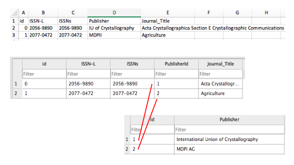
In the example ERD above, creating a separate table for publishers and linking to it from the journals table via PK and FK identifiers allows us to normalise the data and avoid inconsistencies. If we used one table, we could introduce publisher name errors such as misspellings or alternate names as demonstrated below.
There are a number of normal forms in the normalisation process that can help you reduce redundancy in database tables. Study Tonight features tutorials where you can learn more about them.
Additional database design tutorials to consult from Lucidchart:
Keypoints
- Database design is helpful for creating more efficient databases.